Simple Six-Band Shortwave Receiving Antenna
When John Wilson wrote this for The Guide, I added that the Six-Band Sagger is an aerial system and not a medical condition.

This is a simple-to-erect, high-performance aerial system, designed to be erected by the average man using the average house standing in the average garden. In contrast to many fancy ideas about rotating aerials and high masts, the simple six-band sagger presents an elegant solution to the listener's eternal problem. How can I erect a decent aerial system?

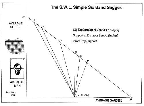
From the drawing, you can see that the aerial support is made of nylon or polypropylene rope, stretched between the ridge point of the house 30 feet off the ground down to a tent peg or solid point at ground level 40 feet away. This makes the classic 3 : 4 : 5 triangle and theoretically the support will be 50 feet long. Clearly, due to the weight of the aerials the support will sag and be longer than 50 feet, but this has been allowed for in the drawing.
Mark the top of the support point on the rope by wrapping a piece of PVC insulating tape around the rope, then measure off and mark points in a similar way at 3, 7, 14, 20, 23 and 27 feet away from the support point. Thread six egg insulators on to the rope and securely bind one to the rope at each measured point. From the insulators tie the aerial wires (which can be any insulated, multi-strand wire) of the following lengths:
| Band | Length Required |
|---|---|
| 49m and 41m bands | 38 feet |
| 31m band | 32 feet |
| 25m band | 25 feet |
| 19m band | 20 feet |
| 16m band | 17 feet |
| 13m band | 15 feet |
Erect the support rope and ensure that all six aerial wires are hanging straight down. Construct the ground terminating point as per the drawing right, making sure that the earth side of the SO239 socket is firmly bonded to the bracket and metal pole.
It is essential that this is earthed, so don't use a wooden pole.
Gather the bottom ends of the six aerial wires and arrange them in a symmetrical fan shape. Strip the ends at the appropriate point, twist together, and solder them to the centre teminal of the SO239 socket. There was enough wire specified in the table above to allow plenty of length in hand, so you will be cutting about 4 - 5 feet off each aerial as you teminate it.
Connect a coax line (50 ohm) from the S0239 socket back to your receiver and voila! You now have a really good aerial system with little trouble and little cost.
How It Works
The aerial system consists of six quarter-wave verticals, one for each major short-wave band, fed aginst earth. The feedpoint impedance is low on each band, allowing the use of coaxial cable from the aerial feedpoint to the reciever. It works a treat, believe me.
After you have been listening for some time, you may find yourself specialising on a certain band. An HF Airband or the 20m Amateur Band or what you will. It is quite possible to design a simple wire aerial which is tuned, or resonates, around your favourite band. The simplest of these is dipole or doublet aerial. Details of these can be found in the early pages of your Instruction Manual, or if you wish to delve deeper, the Radio Society Of Great Britain publishes many a tome on the subject. And you'll find out a bit more as you look around this site...
Remember a resonant aerial takes on directional properties, whereas a wire which is long in relation to the wavelength in use will have multiple lobes in all directions. Your radio will only be as good as the aerial you can give it.
John Wilson - 1982